Overview
I have been setting up Home Automation throughout my unit over the last couple of years. This is an overview of a project to use an ESP-8266 (specifically an ESP-01) to replace my previous room sensors with a cheaper and more elegant one based on this chip.
Background
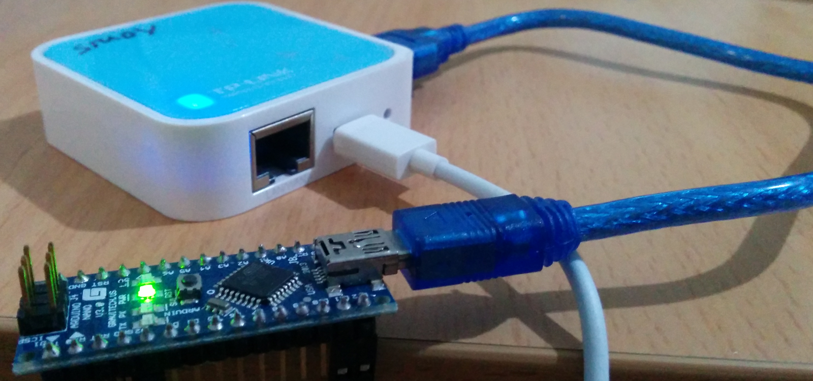
When I first started, Wifi Shields were expensive and attached to the shield pins of Arduino UNO's etc which were themselves not cheap. So to get a wifi enabled Arduino I connected a Nano to the USB port of a TP_Link, as you can see it is not pretty but it did work.
Enter the ESP8266
When the ESP first came out it looked vaguely useful but talking to it over an AT command set didn't look much better than the TP-Link hack, it was a lot cheaper than the TP-Link but I would still need the Arduino. Many people who were playing with them were finding them frustrating to get working, so I didn't put much effort in myself.
Fast forward many months and I find out that the ESP is a pretty descent Microcontroller not just a cheap TTL to Wifi adapter, now I realise I can replace both the TP_Link and the Nano with a single chip if I can get wit working - this is interesting.
NodeMCU
I struggled to get the ESP to a behave well. Every time I got some progress, a previous step would start behaving erratically again. I had given up in disgust until Scott mentioned the NodeMCU devkit which has open source, including the board designs, and available on ebay for about $12.00.
I ordered one of those and within a couple of hours I had success. A LUA script running that could read a motion sensor(PIR), Temperature/Humidity Sensor(DHT22) and a Door Sensor (Reed Switch), then send the readings to my Home Automation System (FHEM). The result is one device, much neater and substantially cheaper.

ESP-01
I was happy with this for a while (about a week ;-), however LUA eats memory and that meant that I had to pull some hacky timing tricks to get all the sensor messages sent (and even then there were glitches every couple of days). At roughly the same time Kris had made progress in getting the ESP-01 to be reliable. So armed with knowledge from Kris and the circuit diagrams from the NodeMCU devkit I found the surprisingly easy answer to getting the ESP-01 to be reliable.
- You MUST have a good 3.3v high(ish) current power supply, unstable power will cause pain and suffering! I used AMS1117 something like this
- Add a 100uF(3) resistor between VCC and GND
- Add a 12k(2) pullup resistor to GPIO0 and GPIO2(1)
- Add 12k(2) pulldown resistor and a 470pF(3) capacitor to RESET.
(1) For flashing the firmware pull GPIO0 low instead of high
(2) The value (and possible even the need) of the resistors and capacitors may be able to be changed, but I copied them from the NodeMCU circuit to minimise risk
(3) These may be able to be lower values, but again I've used the NodeMCU as my reference design
ESP8266 and Arduino
Additionally, by this time a port of the Arduino development environment for the ESP8226 had been created and had become stable. So I could now write all the code in a compiled language in an environment I was already familiar with.
The Software
Assuming you are familiar with Arduino programming the code is fairly easy ad can be found here - Sensor Code
One tricky bit is that that ESP-01 only has two pins that are 'meant' for Input/Output and I need 3 pins, one each for the DHT22, the PIR and the Reed Switch. However, you can use the serial pins as GPIO pins as long as you don't need serial input/output - which I don't. To develop the code I put each sensor on one of the proper GPIO pins so that I could use the serial terminal while debugging. Once I has the code for each sensor working I pulled the serial code out and put one of the sensors on a serial pin.
The Sensors
A DHT22 for Temperature and Humidity - DHT22 on ebay
A PIR Sensor motion - PIR sensor on ebay
a Reed Switch for the door - Reed Switch on ebay (link to single listing may disappear)
A Circuit Board
The HackerSpace has a small CNC that has been very useful for creating circuit board. Creating a Circuit with Eagle, PCB-GCode and a CNC initially looks like it will take longer than just breading-boarding up a prototype, however I've found the opposite to be true. Designing the circuit properly and avoiding the tangled mess of unreliable wires that happens when breadboarding means that I get a working prototype faster, and as a bonus I'm much closer to a production board when I have the prototype done.
The board comes out fairly well, however I'm a poor solderer and the these copper etched boards are harder to solder than professional boards. I found that a light rub with sandpaper along with heaps of flux helps. The board I used for my prototype on the CNC is single layer as doing two layer boards on a CNC is considerably more fiddly (I've never done it)
<INSERT_PIC_OF_BOARD>
The board I send sent to Seeed Studio for manufacturing is two layer. I made some layout changes and one minor circuit change for the production version.

The Board designs are here:-
A case
To get a reasonable looking case in which to put the sensor I designed a simple case and then printed it on my 3D Printer. The case was design in Alibre, because I know it and it was good value for money when I bought it. Links to the Alibre file and the STLs are below
Below is a picture of one of the early prototypes, I hasn't been printed to get the best quality and the sizes are a bit out.

Finished
Here is the completed node on the wall.

And here's a picture of the graphs for Temperature, Humidity and motion from my Study.

Comments (0)
You don't have permission to comment on this page.